In an attempt to build my own laser-scanner/project i’ve googled alot… which is kinda what most it’ers do when solving stuff.
Anyhow most of the people that are into lasers and shit, are know with Elm-Chan’s project, which basically means buidling your own galvanometers and analog drivers. Since my litte appartment didn’t came with a broad set of vertical drills, milling machines and lathe’s to craft the stators of the galvano’s… I didn’t bother trying it. Another difficulty is my somehow limited analog electronics skillset… (but hey, if your writing ruby/java and mongodb queries all day..). Anyway. Chan’s path was not mine to take.
Scanlime
Then I came acros this little project, which is kinda unique in the sens that most if not all laser-systems are build using analog components, especially the closed-loop (which you want due to obvious reasons… feedback anyone?) where is this one fully digital: scanlime
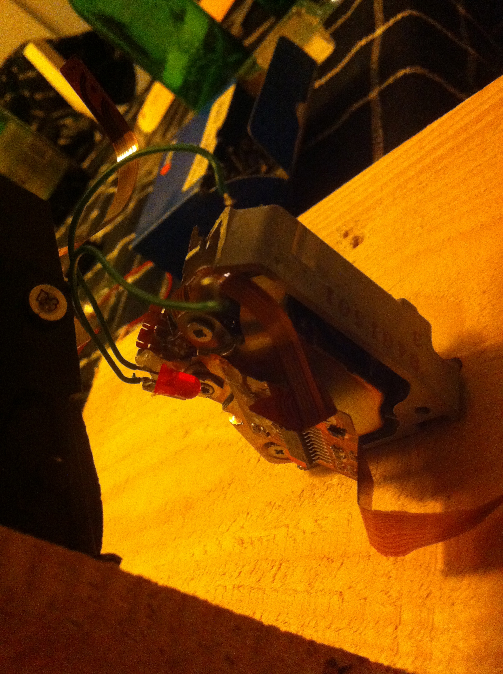
Anxious to get cracking, I grinded some harddrives into piece, helped by friend (Thanks Laurens!). and made it some how into an X- Y system:
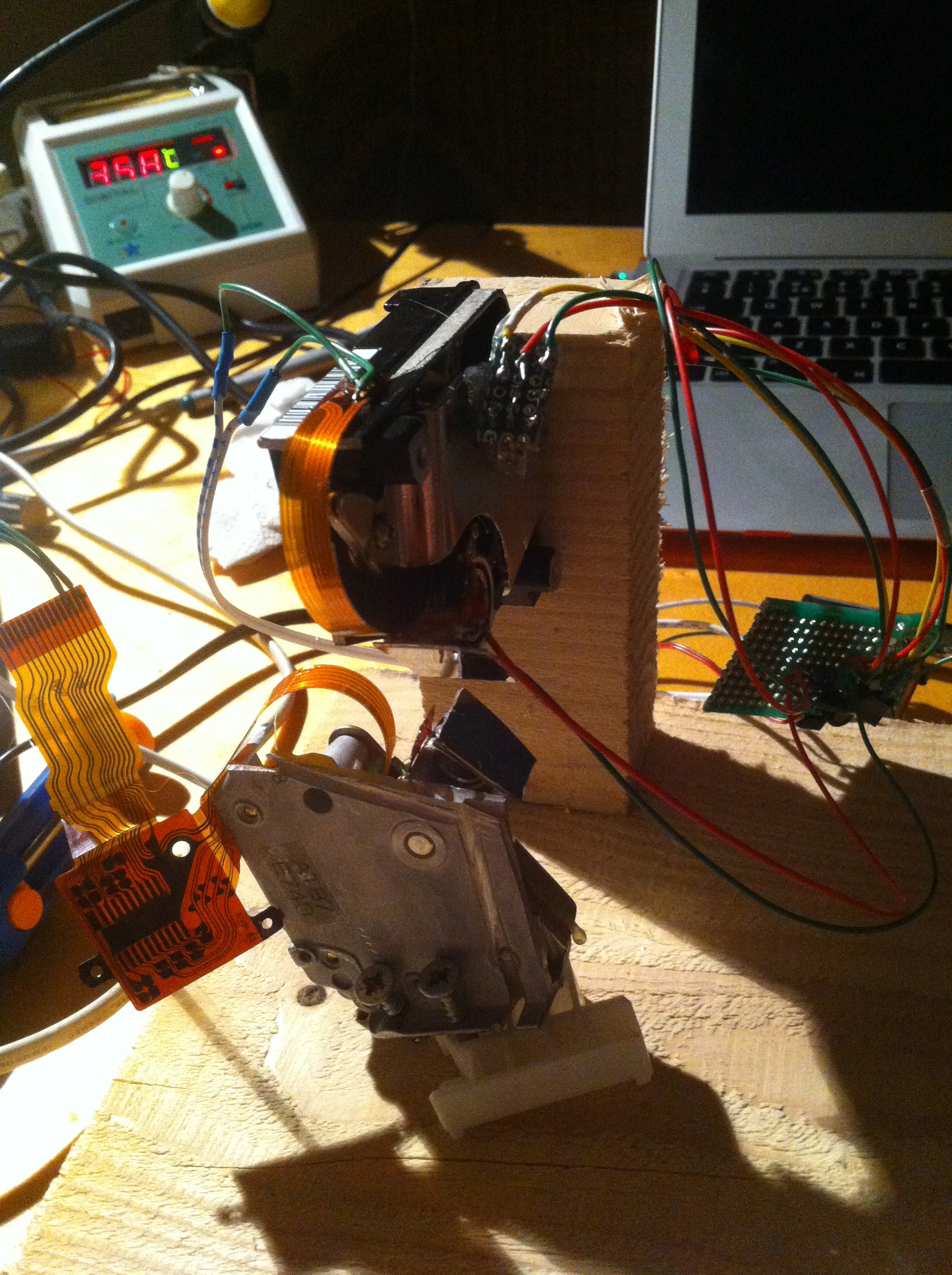
In the picture you see the harddrive lower-richt corner. There is an led attached to the rotating axis (well… 40 degree at most).
After grinding the motors I attached the Led.
Each led provides an beam of light, which diminishes when you go further rotated it away from it’s orthogonal position. Using a TSL235R sensor, we can measure the intensity of the signal, digitally :), this sensor generates an 50% dutycycle between ? and 100khz @full saturation.
So sampling the time between up-going/faling edges, we can measure the intensity of the light and therefore the position.
So, now we have a way of figuring out the position of our axis/mirror, we can proceed on drive the mirror in a position we like :)
By using PWM (Pulse-width-modulation) and a H-bridge schema, we can drive these harddrive motors (which are linear motors) quite easily. But as they have no ‘neutral’ position, you’ll just yank them towards there mechanical max position when applying current.
In order to position them in a arbitrary position we need to alternate the current given the current position. This is where our trusted PID (proportional-integral-derivative) controller / software implementation comes in, please search wikipedia should you care to read more.
What PID basically does is set an output value, compare this value with the current position, calculate a error (difference between desired position and actual position) and update the output accordingly, it also takes the ‘time’ into consideration. When an PID loop is well-tuned, it is the fasted way to get at an desired output state without much (if any) overshoot.
Obviously these calculation need to be done fast and often.
To give you some sense of dimension: a (crappy) 12k scanner does 12.000 point/s given a particular angle. In sampling in the digital systems an sampling rate of 2(f) (2x the frequency) is considered bare minimum. As 12.000 points means go 12.000 times per second from point a to point b… this leave 0,00008333333333 seconds per point transition. If we where to need 12 samples per transition to become ‘stable’, we would need AT LEAST 24 observations of the current position. This would mean every 0.00000347222222 second, we would have to calculate an PID loop PER AXIS.
This would mean on a 16mhz micro-controller, that ~ 55 clock/cycles would be ‘free’ to do this calculation…… Is not going to happen as we have 2 axises, floating-point math, switching between reading positions, frames (the drawing for example), and various other stuff.
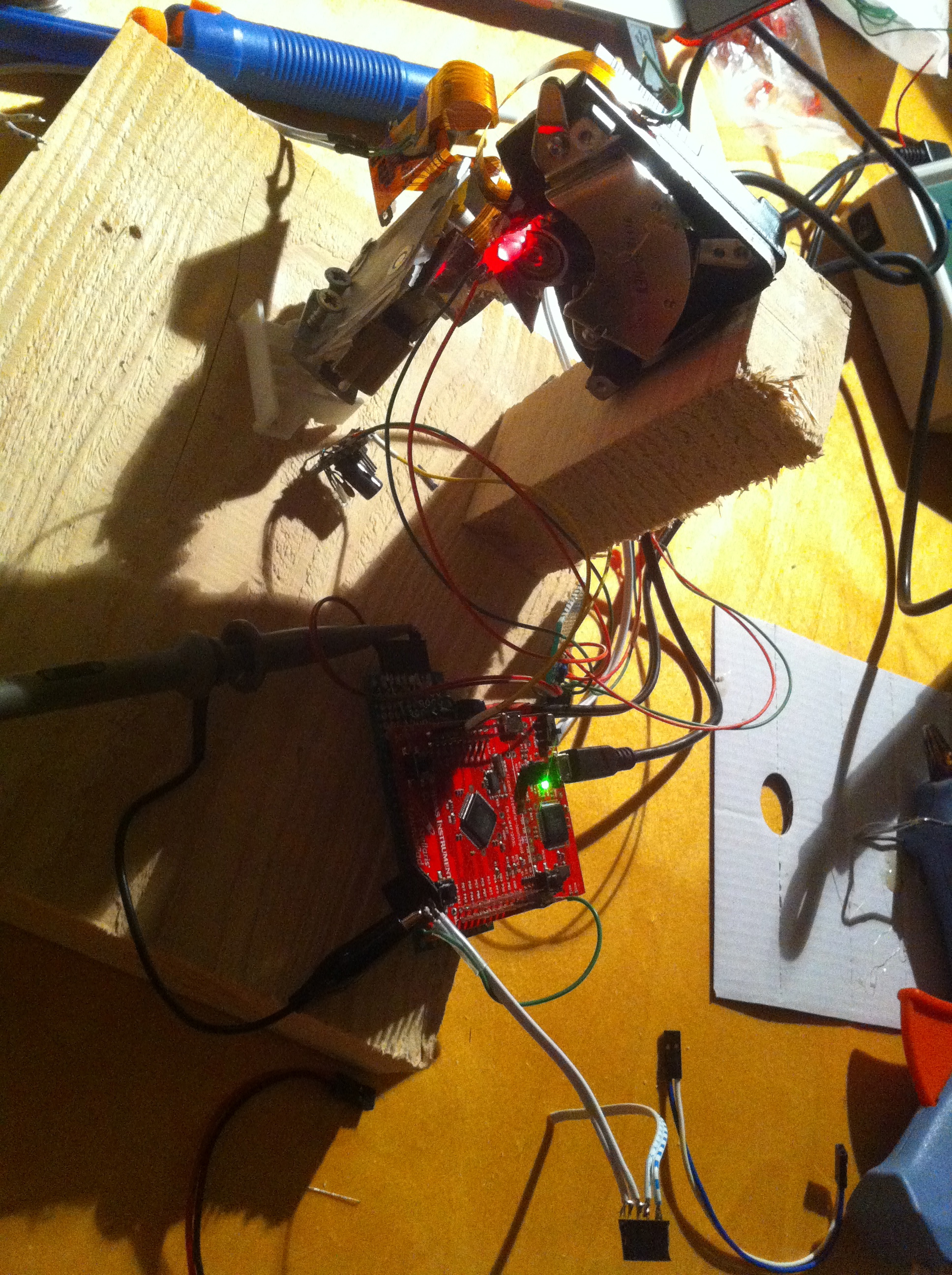
That’s why I choose the Stellaris cpu, which is with 80mhz consideratly faster, has a fpu (floating point unit), 32bit memory and all kinds of nice features, still SLOW (for this case, but less).
So after configuring the PWM outputs on the stellaris (technically, the stellaris has no real pwm hardware, but it features two timers, both 16-bit, which can be split into 2 8bit units.) Using these timers to drive the H-brug and a digital pin for the direction of the current, I was able to run calibrate routines, and position the actuators on a set point.
However due to lack of a proper H-brug (not the crapy eBay unit) and 2 distinct current sources, I stopped working on this project. I had proven that I could position the motors, and drive the lasers’ position. BUt as it was way to slow for this single-core unit, I stopped.
I decided to buy 20k proper galvanometers, the necessary drivers for them, power supply and other necessities, and build a more ‘convenient’ setup. More on these setup to follow.
For those still interested in the code for the Stellaris: please checkout my github (oh and my C is a bit rusty… so no promisses)

Share this post
Twitter
Google+
Facebook
Reddit
LinkedIn
StumbleUpon
Pinterest
Email