Having experienced some major WIFI problems over the years, with the overly crouded 2.4 ISM band. I decided to dust of the good old CC2500 chip, and get it running, properly. The reason for this chip? the 8-bit RSS value you can acquire from it. These day’s, the very cheap NRF24L01+ is rather nice, and cheap, but with a 1bit RSSI ‘threshold’, not very useful for these kind of setups.
Therefore I decided to build my own RF-Spectrumanalyser.
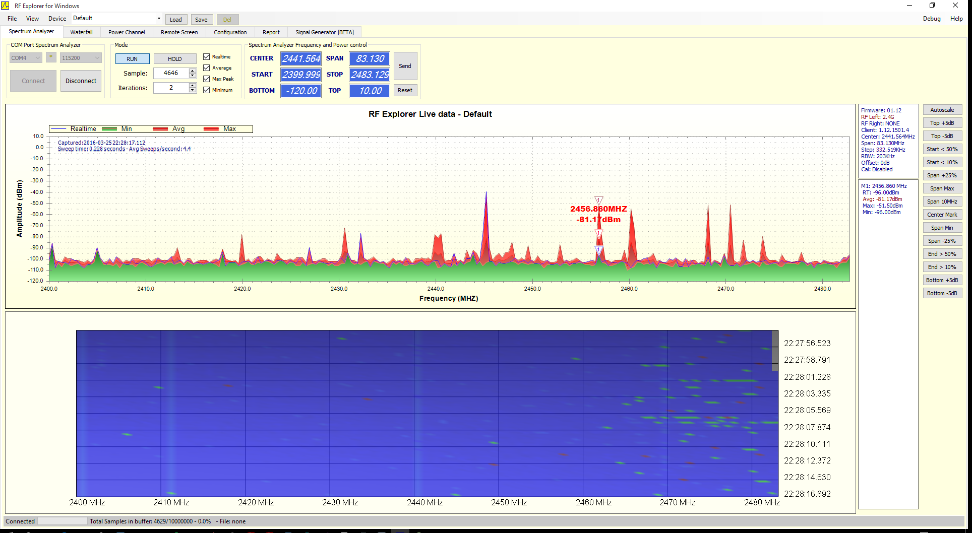
So after a bit of googling, i found this rather sweet piece of hardware, the RFExplorer, and even nicer, the open-source PC-hardware, that is available, Arocholl-RFExplorer at github. The developer of the hardware even included a nice RS232 API, how to communicate with the device.
As I really like to build stuff, and when finished, not actually use it, i thought, why not emulate this hardware, this saves me the trouble of extensive programming on the GUI which probaly be worse. Having some relatively detailed info from the API, exposed by the RFExplorer’s dev, I started of implementing some stuff in the Arduino.
Using a Arduino pro mini (probably not genuine), from eBay, clocked at 8Mhz, and 3.3V’s, I can just wire it up with the CC2500, without any level shifting, do keep this in mind, both for clocking, but also 3.3V, the CC2500 isn’t 5V tolerant! The CC2500 has a max CLK freq. of 10mhz, 6.5 when in burst, so keep this in mind, when using a faster MCU.
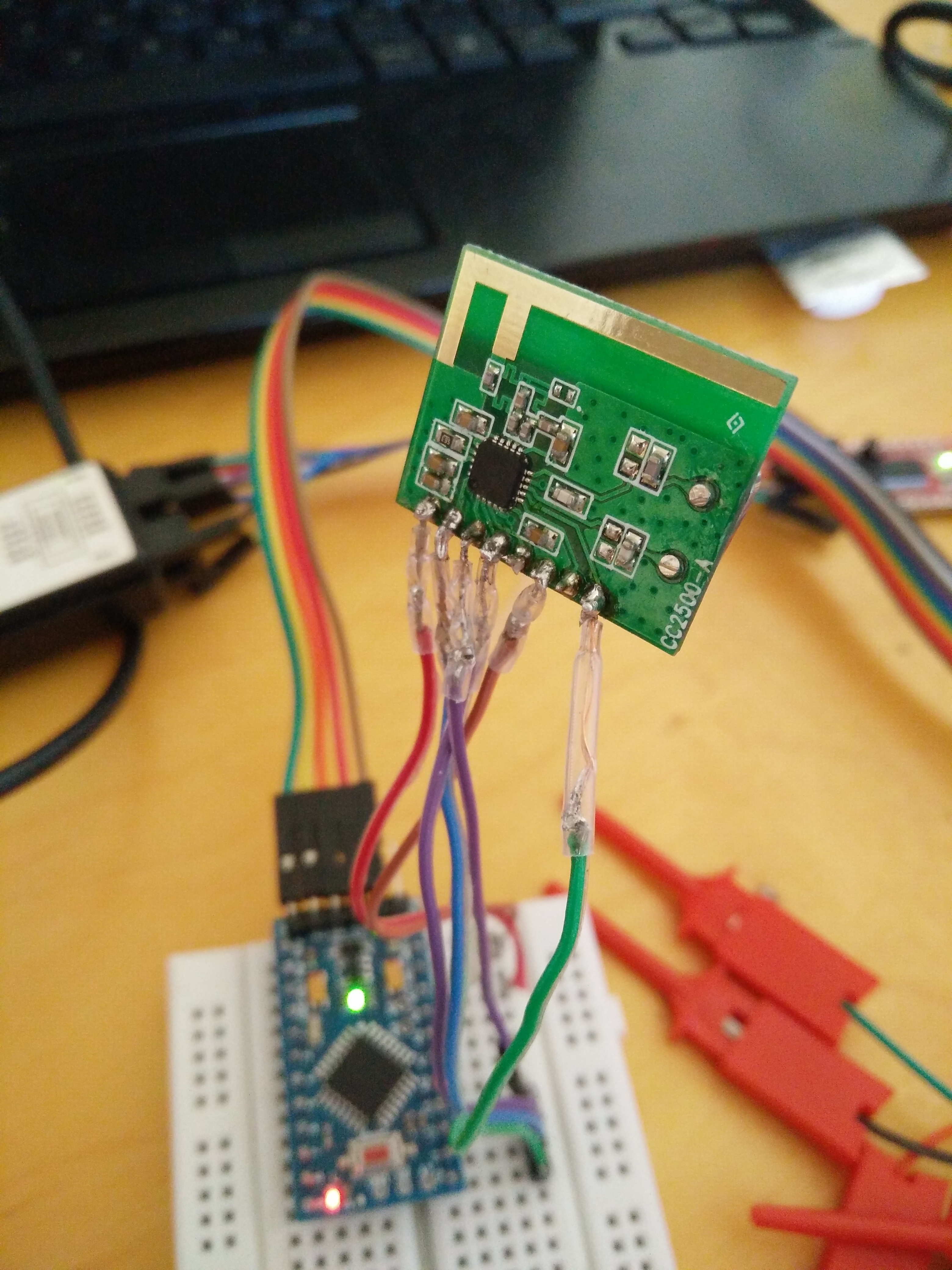
Reading a lot of stuff, and code I finally managed to get it working probably. I can definitely recommend using the RFStudio to calculate your registers, as this CC2500 consist of +-40 registers, not a great experience to configure/calculate them all by hand!
Making the PC-code communicate with the Arduino
In order to communicate with the Arduino, I needed to make some alterations to the RF-explorer code. The RFExplorer hardware apparently consists of Cyprus RS232 chip. As I dont have this chip, but rather use a FTDI chip, I changed the low-level code to search for other USB-id’s:
After making this alteration, we also needed to make the baud rate work with 115200, instead of the Cyprus settings, which is set in one of the forms.
Optimalisations
In order to make some speed improvements, I’ve implemented a calibration routine, which calibrates all the pump, and frequency synthesizers and PLL, and stores the resulting registers. These are put back in registry before channel switching. This reduces the channel switching delay from ~910 uS, to about 100 uS
The result
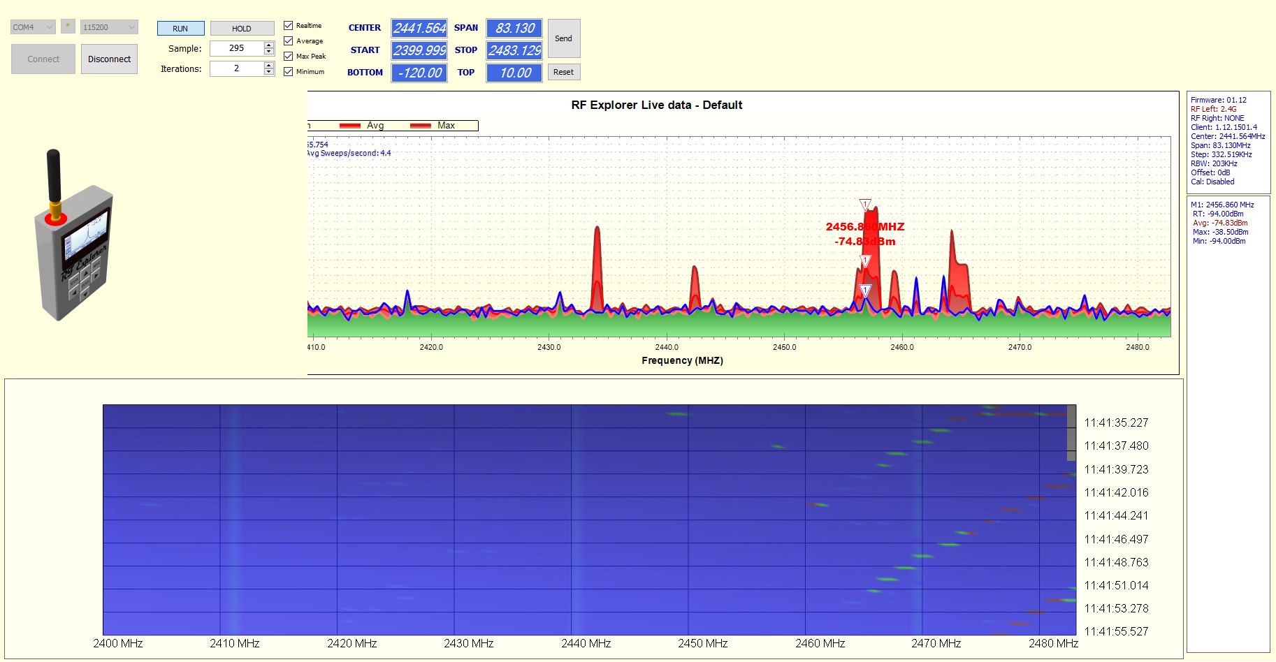
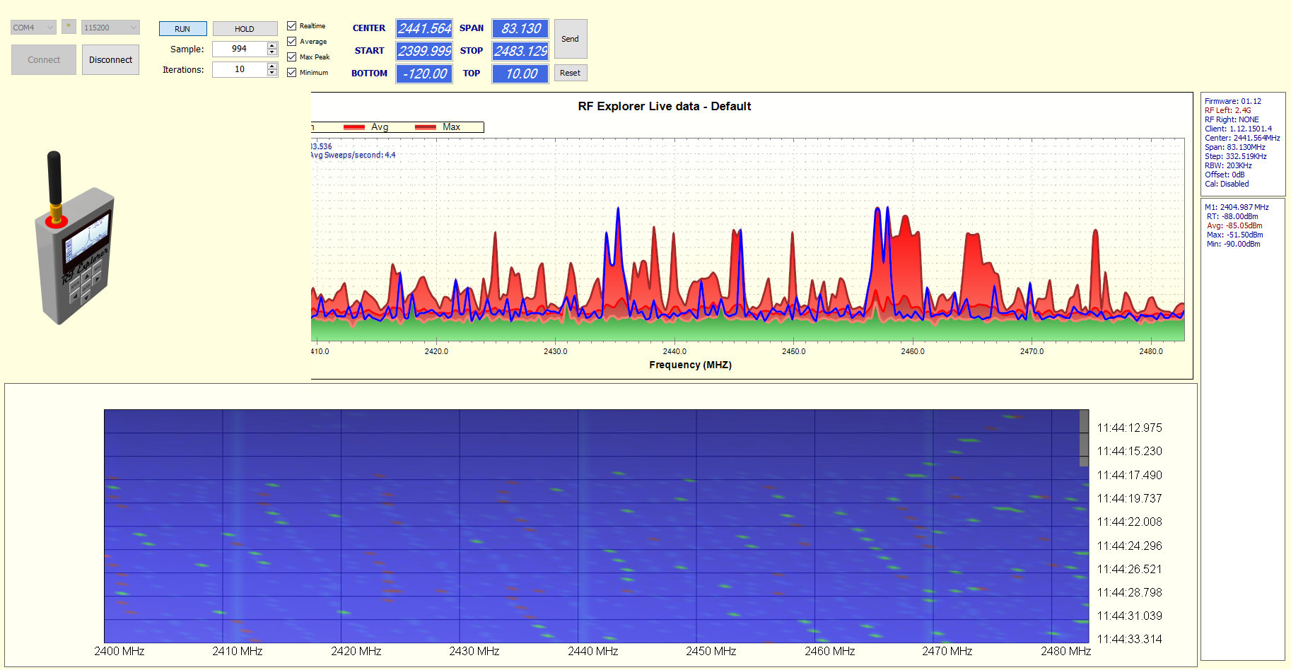
I must say, the result is rather satisfying, it is not particular fast, with 4.5 full sweeps/second, compared with a RTL-SDR, but it does scan 250 channels every sweep, with a 2$ radio chip.
Do keep in mind, that remotely comparable solutions start at >200$ for the 2.4- 2.483 band
usability
It already has given quite some insights regarding usage in my apartment. there are 2 continuously transmitting, device near the 1 freq. band, and sequential frequency hopping device, which I haven’t located as of yet, but the search continues! Furthermore I can confirm that some of the cheap Chinese remote controls, (which i use for my drone), do some excessive channel hopping, using the whole 2.4 band… and making it light up like a chrismastree (in waterfall mode), so perhaps limit the usage indoors :P
For those interested in the code: https://github.com/VincentGijsen/RFExplorerArduino (the code used in the Arduino) https://github.com/VincentGijsen/RFExplorer
Please keep in mind, my code+hardware works somehow work, but it lacks a lot of features of the original product, as well as any calibration done (I don’t posses any hardware for verifying my configuration, software and settings). If you like the software, do consider buying the real RFExplorer, and in doing so supporting the original author(s)

Share this post
Twitter
Google+
Facebook
Reddit
LinkedIn
StumbleUpon
Pinterest
Email